
We’re going to be learning how split phase electricity supplies work to get both 120V and 240 Volts. We’ll look at how the electricity gets from the power station and to the property and then how it is connected around the house and each of the main components.
Warning
Remember electricity is dangerous and can be fatal, you should be qualified and competent to carry out any electrical work. Never work on hot/live electrical circuits.
So electricity is generated at the power station which is usually located far away. The power station generates AC alternating current and is connected to a step up transformer, this transformer increases the voltage to reduce losses and is connected to the grid. The grid carries high voltage electricity over long distances over to the towns and cities.
Once it reaches the towns and cities it will enter a step down transformer which will decrease the voltage to a safer level. From here it will be distributed locally into smaller circuits on different streets or groups of properties.

Connected to these distribution cables will be a smaller transformer, usually pole mounted, which again reduces the voltage down even further to a level safe enough for residential use. On the property will be an electricity meter which will quantify how much electricity has been used and the electricity company will use this to invoice you.
The transformer will be connected to the electricity meter by some cables which either runs underground or overhead. These cables will be two hot wires and a neutral wire.

Inside the transformer we have two coils of wire. The primary coil is connected to the power station and the second coil will be connected to the property. The two hot wires are connected to each end of the secondary coil and the neutral is connected to the center of the coil.
Inside the property (sometimes outside) we will find a main service panel which is often also called a load center or breaker box.

If we remove the cover and look inside, we will first find a main breaker. This is usually at the top of the panel but it might be at the bottom. The two hot wires from the electricity meter will connect directly to the lugs on the main breaker.
Coming out of the main breaker will be two main bus bars. These are basically exposed metal sheets which carry electricity to the circuit breakers.
These bus bar metal sheets, as well as the lugs, are not insulated, they are live/hot. The main breaker can be manually flipped to cut the power to everything downstream of the main breaker. The main breaker will also provide overcurrent protection to the property, it is rated to handle a set amount of electrical current passing through it typically between 100 and 200 amps, if this is exceeded then it will trip automatically to try and protect the property and electrical circuits.
Inside the panel we will also have a neutral and ground bus bar. This is basically a strip of metal with lots of holes and screws in it. The neutral and ground wires will sit in the holes and the screws lock them in place.

In this example we have a block on either side of the panel. As this is a main panel the two bars can be joined together (Check with the NEC for exact details), so we have the connector bar to join the two bus bars. That way we have a shared neutral ground bar.
From the electricity meter we will have the neutral wire connected to the lug on top of the neutral ground bar. Notice the green screw, this is bonding the neutral bar to the metal casing of the service panel.
The purpose of the neutral bar is to return the used electricity back to the transformer. It does actually get a little more complex than that because current is flowing backwards and forwards in AC current.
So the two hot wires will provide the electricity and once it is used it will return to the transformer via the neutral bar.
Now if we were to take our multimeter and connect one lead to a bus bar and the other lead to the neutral bar, we would get a reading of around 120V. If you don’t have a multimeter then I highly encourage you to get one for your toolkit, it’s essential for any electrical testing and fault finding.
If we connect the multimeter leads to the other bus bar and the neutral bar we would again get a reading of around 120volts.

But if we connected the multimeter leads to the two bus bars then we will get a reading of double that at around 240 volts.

So why is that, what’s happening here?
So when we look at how the transformer is connected to the main panel. We have the two hot bus bars connected to either end of the secondary coil in the transformer and then we have the neutral bus bar connected to the center of the secondary coil.
So basically when we connect across one bus bar and the neutral bar, we are only using half the coil, therefore we are only picking up half the electrical voltage the transformer can provide and we get 120 volts.
When we connect to the two bus bars we are connecting to the full length of the coil so we can pick up the full voltage which the transformer can provide. Therefore we get 240V.
Refer to: Paul Evans, TheEngineeringMindset.com
OPzV Tubular Gel Battery
OPzV Tubular Gel Battery
HPS Series Solar Inverter
HPS Series Solar Inverter
MRS Serires Solar Inverter/ Charger
MRS Serires Solar Inverter/ Charger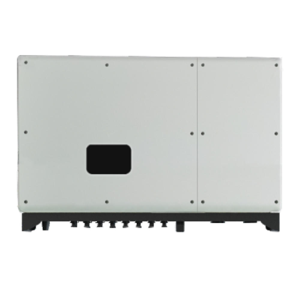
37KW-55KW Three Phases Solar Pump Inverter
37KW-55KW Three Phases Solar Pump Inverter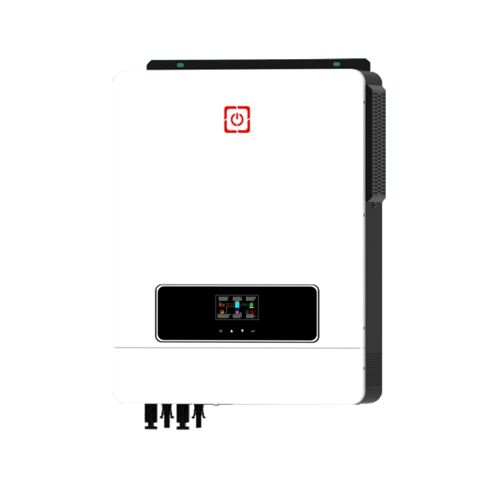
MHC Series Solar Inverter
MHC Series Solar Inverter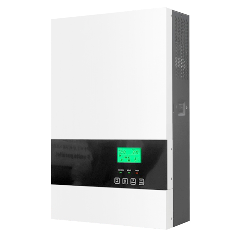
MPK-III Series Solar Inverter
MPK-III Series Solar Inverter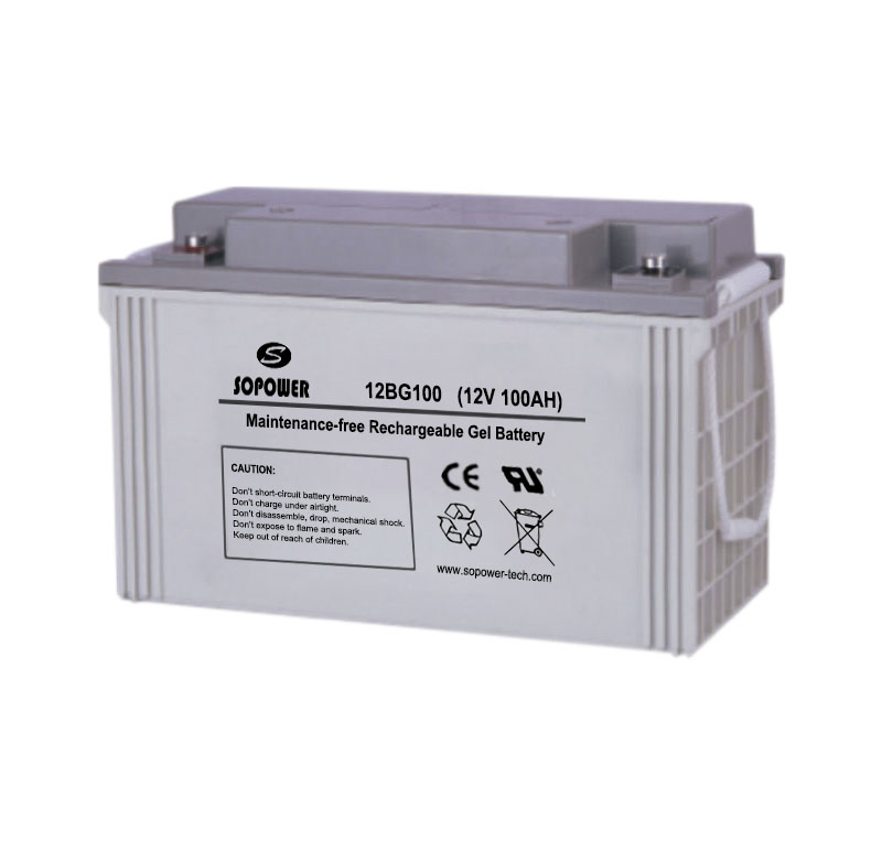
Gel Battery
Gel Battery
TG Series Three Phases On Grid Solar Inverter
TG Series Three Phases On Grid Solar Inverter
Front Terminal Battery
Front Terminal Battery